    
|
||||||||||||||||||||||||||
|
||||||||||||||||||||||||||
|
||||||||||||||||||||||||||
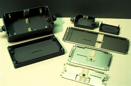
| Materials of construction | |
| Lid | Die cast aluminum with baked enamel finish |
| Enclosure | Die cast aluminum with baked enamel finish |
| Connectors | Nylon with neoprene gland |
| Working Temperature Range | -30° - 70°C |
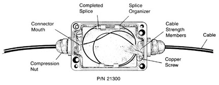
| P/N 21300 (for up to 6 splices) | |
| Dimensions for enclosure | 3.5" x 2.5" x 1.75" |
| Weight | 8 oz. |
| Cable Diameter Range | .187" - .312" |
| P/N 21310 (for up to 18 splices) | |
| Dimensions for enclosure | 8.75" x 4.75" x 3.25" |
| Weight | 47 oz. |
| Cable Diameter Range | .236" - .512" |
Assembly Procedures
A. Before making splice
1. Loosen outer screws to remove the coverplate from the base and set it aside.
2. Loosen both compression nuts from either side of the enclosure and insert fiber cables.
3. P/N 21300 (for up to 6 splices) - Strip away 11 to 12 inches of insulation from both cables. P/N 21310 (for up to 18 splices) - Strip away 28
to 30 inches of insulation from both cables.
4. After the insulation has been removed,pull the cables back so that the end of the insulation is flush with the mouth of the connector. When
the cables are in position, tighten compression nuts to hold in place.
5. Clamp the cable strength members underneath the copper screws.
6. Trip off excess cable strength members.
B. Assemble splices according to procedure.
C. After splice is completed.
1. Take the completed splice and loop the fibers inside the enclosure. Keep fibers down by tucking them underneath the splice organizers in
P/N 21300 or in wire saddles in P/N 21310.
2. Clip the splice onto the organizer.
3. Install coverplate and tighten screws into place.
[ Download Product Data Sheet ]
Home - Adhesives - Fiber Optics - Fish Gel - Distributors - About - Trade Shows - Employment